Instrumentation · 10 min read · Updated October 2026
RTD vs Thermocouple: Differences, Accuracy and How to Choose
Pt100 or type K? Compare accuracy, range, stability and wiring at your real operating point, and avoid the installation errors that matter more than the sensor itself.
RTDs (resistance temperature detectors, most often Pt100) and thermocouples are the two most widely used industrial temperature sensors. The difference between RTD and thermocouple goes beyond price: they work on different principles and differ in temperature range, accuracy, long-term stability, response time and wiring. Choosing the wrong one can add several degrees of error, shorten sensor life or make a control loop oscillate. This guide compares the two side by side, gives selection rules per application and lists the wiring mistakes we most often find on site.
Quick answer: RTD or thermocouple?
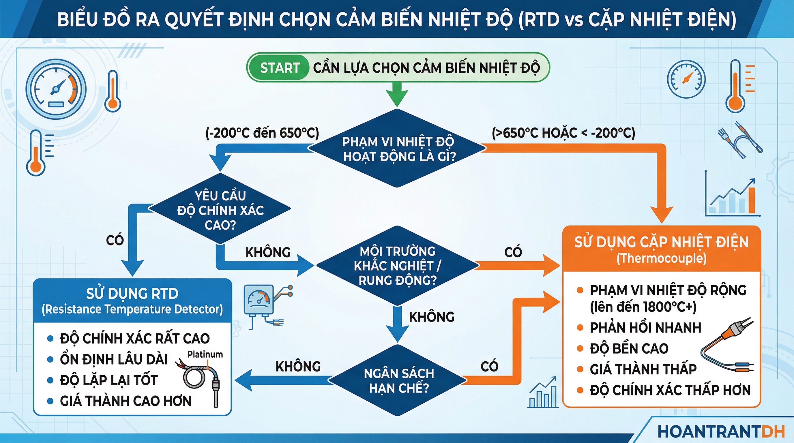
- Choose an RTD (Pt100/Pt1000) below about 400–600 °C when you need accuracy and long-term stability: water, oil, saturated steam, food, pharma, HVAC, cold rooms, bearings and motor windings.
- Choose a thermocouple for high temperatures (furnaces, flue gas, metals, ceramics, glass), when you need a very small probe or fast response, or under heavy vibration.
- Between 400 and 600 °C both work: prefer an RTD for accuracy, a type K or N thermocouple for robustness and cost.
1. How each sensor works
RTD: resistance changes with temperature
An RTD relies on the fact that the electrical resistance of a metal rises with temperature. Platinum is used because its resistance–temperature curve is very stable and repeatable. A Pt100 has 100 Ω at 0 °C and rises by about 0.385 Ω per °C (α = 0.00385 per IEC 60751). A Pt1000 has 1000 Ω at 0 °C, which makes it ten times more sensitive and much less affected by lead-wire resistance.
The instrument passes a small excitation current (usually below 1 mA) through the element, measures the voltage drop to obtain the resistance, and converts it to temperature with the Callendar–Van Dusen equation.
Thermocouple: voltage from two dissimilar metals
A thermocouple is two different metal wires joined at one end (the measuring or hot junction). A temperature difference between the hot junction and the cold junction (where the wires connect to the instrument) produces a voltage of a few tens of microvolts per °C, known as the Seebeck effect. Type K gives about 41 µV/°C.
The key point: a thermocouple measures a temperature difference, so the instrument must measure the terminal temperature and add it back. This is cold junction compensation (CJC). A thermocouple needs no excitation because it generates its own signal.
2. RTD vs thermocouple comparison table
| Criterion | RTD (Pt100/Pt1000) | Thermocouple (K, J, N, T, S, R, B) |
|---|---|---|
| Temperature range | About −200 to 600 °C (some designs to 850 °C) | About −200 to 1700 °C depending on type; type K continuous to about 1200 °C |
| Accuracy | High: Class A ±(0.15 + 0.002|t|) °C, e.g. ±0.35 °C at 100 °C | Lower: type K Class 1 ±1.5 °C or ±0.4% of reading, whichever is greater |
| Long-term stability | Excellent, drift typically below 0.1 °C/year in normal service | Poorer; type K can drift several degrees after long use at high temperature |
| Response time | Slower, because the element has physical size | Fast, especially grounded-junction, small-diameter probes |
| Vibration | Wire-wound elements are sensitive; thin-film is more robust | Good, simple construction |
| Probe size | Usually Ø3 mm and larger | Can be very small (Ø0.5–1 mm) |
| Power | Needs excitation current from the instrument | Self-powered signal |
| Wiring | Ordinary copper, 2-, 3- or 4-wire | Matching extension/compensating cable, correct polarity |
| Signal | About 0.385 Ω/°C (Pt100) | Tens of µV/°C, easily affected by noise |
| Sensor cost | Higher for the same construction | Lower (except noble-metal types R, S, B) |
3. Understanding accuracy correctly
Sensor tolerance grows with temperature, so always compare at your actual operating point:
| Temperature | Pt100 Class A | Pt100 Class B | Type K Class 1 | Type K Class 2 |
|---|---|---|---|---|
| 100 °C | ±0.35 °C | ±0.80 °C | ±1.5 °C | ±2.5 °C |
| 300 °C | ±0.75 °C | ±1.80 °C | ±1.5 °C | ±2.5 °C |
| 500 °C | ±1.15 °C | ±2.80 °C | ±2.0 °C | ±3.75 °C |
Total measurement error also includes the transmitter or PLC input error, lead-wire error (2-wire RTDs), cold junction error (thermocouples) and installation error such as insufficient immersion depth. In practice, poor installation often causes far more error than the difference between the two sensor types.
4. Common thermocouple types
| Type | Materials | Continuous range | Typical use |
|---|---|---|---|
| K | NiCr – NiAl | −200 to 1200 °C | General purpose: furnaces, flue gas, machinery |
| J | Fe – CuNi | −40 to 750 °C | Plastic injection molding, reducing atmospheres |
| N | NiCrSi – NiSi | −200 to 1250 °C | Replaces type K for long service above 800 °C |
| T | Cu – CuNi | −200 to 350 °C | Low temperatures, laboratories |
| S, R | Pt – PtRh | 0 to 1600 °C | Glass, metals, ceramics |
| B | PtRh – PtRh | 600 to 1700 °C | Very high temperatures |
5. Wiring mistakes that cause wrong readings
RTD
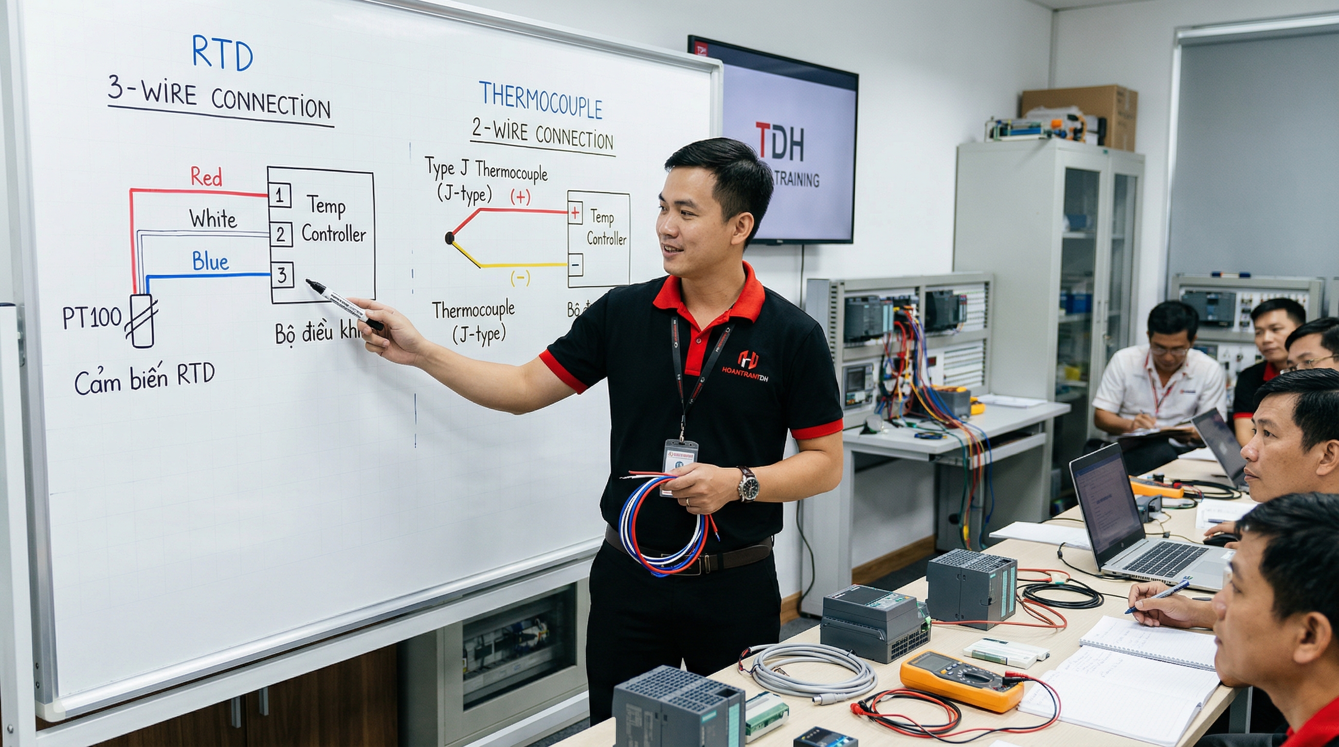
- 2-wire connection over a long cable: lead resistance adds directly to the reading. 10 m of 0.5 mm² cable (about 0.7 Ω for both leads) already adds about +1.8 °C on a Pt100. Use 3-wire in industry, 4-wire for high accuracy, or mount a head transmitter on the sensor.
- Three leads of different size or length: 3-wire compensation assumes all three leads have equal resistance.
- Loose or oxidized terminals: contact resistance makes the reading jump or creep upward.
Thermocouple
- Plain copper wire instead of extension cable: the cold junction moves to the junction box, and the reading drifts with the box temperature.
- Reversed extension cable polarity: error of roughly twice the temperature difference between the junction box and the transmitter — hard to spot because the value still looks plausible.
- Wrong type configured on the transmitter or PLC: setting type J for a type K sensor gives errors of tens of degrees.
- Running in the same tray as power or VFD cables: the µV signal picks up noise easily; use shielded cable grounded at one end.
6. Selection by application
| Application | Recommendation | Why |
|---|---|---|
| Hot/chilled water, HVAC, chillers | Pt100 Class A, 3-wire | Accuracy for energy calculation and control |
| Food, pharma, sterilization | Pt100 Class A/AA, sanitary connection | Accuracy and periodic calibration required |
| Bearings, motor windings, transformers | Built-in Pt100 | Stable, standard for motor protection relays |
| Plastic injection, molds | Type J or K thermocouple | Small probe, fast response |
| Furnaces 600–1200 °C | Type K or N, Inconel sheath | Beyond RTD range, high-temperature rated |
| Furnaces above 1200 °C | Type S, R or B with ceramic tube | Only noble metals survive |
| Cold rooms, freezers | Pt100 or Pt1000 | Accurate at sub-zero temperatures |
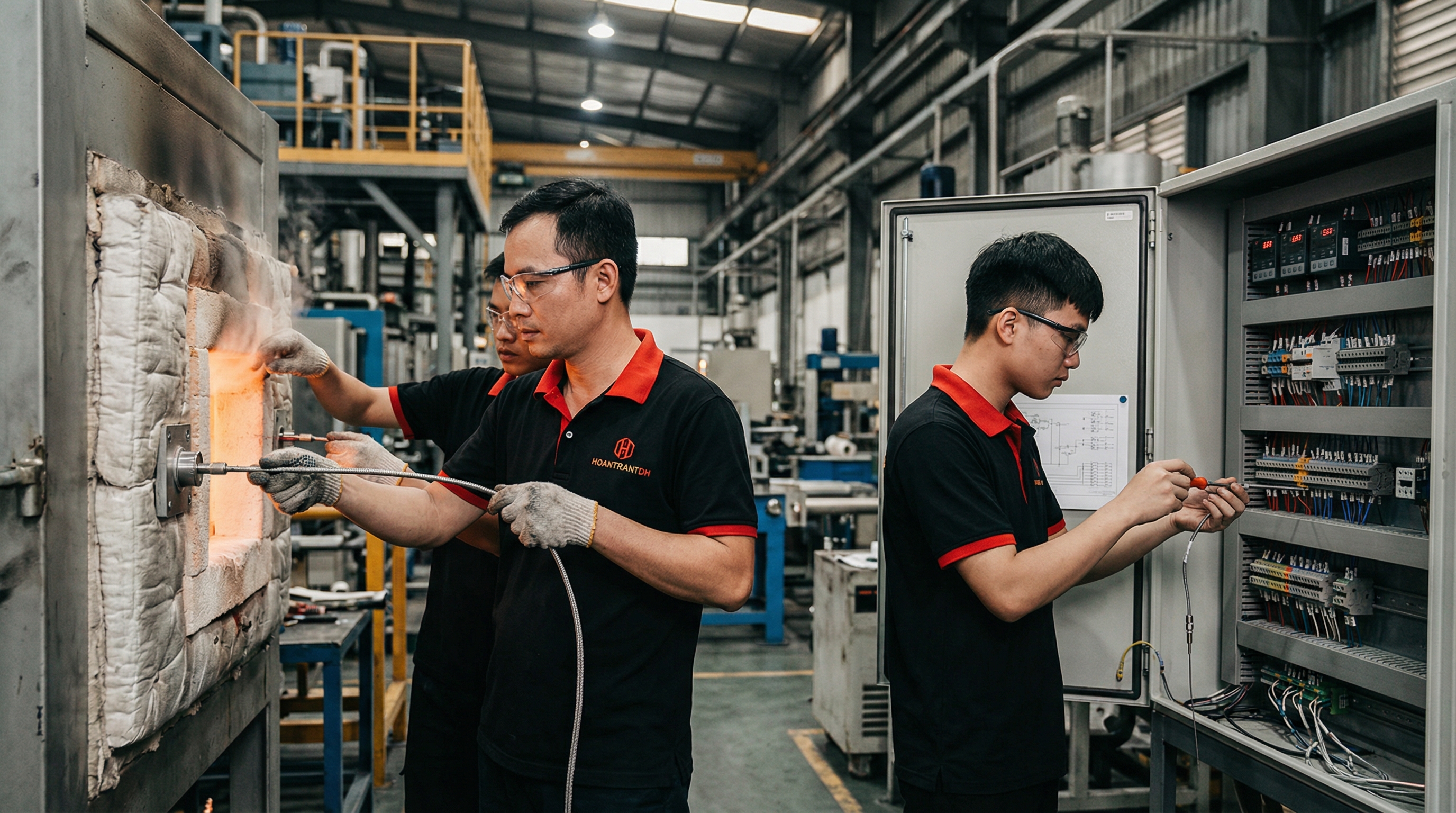
7. Install correctly to measure correctly
- Immersion depth of at least 10–15 times the sheath diameter reduces stem-conduction error.
- Thermowells on pressurized pipes let you replace the sensor without shutting down, but slow the response; choose a tapered tip when speed matters.
- 4–20 mA head transmitters are recommended for long distances to the PLC or noisy environments.
- Quick Pt100 check: about 109.7 Ω at 25 °C; a few ohms means a short, infinite resistance means an open circuit.
- Quick thermocouple check: measure mV at the terminals, add the mV equivalent of the terminal temperature and look up the table. Our free thermocouple table with CJC and Pt100 table do this in the browser.
Quick answers
What is the difference between RTD and thermocouple?
An RTD measures temperature through the change in resistance of a platinum element and is more accurate and stable, typically up to about 600 °C. A thermocouple generates a small voltage from two dissimilar metals, covers much higher temperatures (up to about 1700 °C), responds faster and costs less, but is less accurate and needs cold junction compensation and matching extension cable.
Is an RTD more accurate than a thermocouple?
Yes, within the range where both can be used. A Class A Pt100 at 100 °C has a tolerance of ±0.35 °C, while a Class 1 type K thermocouple has ±1.5 °C. RTDs also drift less over time.
What is the difference between Pt100 and Pt1000?
Same principle and curve; only the nominal resistance differs (100 Ω vs 1000 Ω at 0 °C). Pt1000 is less affected by lead resistance, so it suits 2-wire and battery-powered devices; Pt100 is more common in industry and supported by more transmitters and input modules.
Can I replace a thermocouple with an RTD on the same instrument?
Only if the transmitter, PLC module or controller supports RTD input and is reconfigured. The signals and wiring are completely different.
Why does a type K thermocouple drift over time?
Long service at high temperature changes the alloy composition, and in low-oxygen atmospheres around 800–1050 °C type K can suffer "green rot". For continuous high-temperature duty, type N is more stable.
Need help selecting temperature sensors, transmitters or input modules for your plant? Contact HOANTRANTDH engineering or send your process conditions through the RFQ form.